Pwm 4 Pin Diagram
Conector 4 vias pwm 5 images cpu fan pinout and review Arduino pwm fan controller schematic projects microcontroller based
Preventing EMI and Reducing Noise from High Current PWM Signals
Fan pwm pc 12v wire header guide colours match note only may Arduino pwm fan controller – microcontroller based projects Pwm wiring noise emi voltage modulation grounding instrument controller shielded actuator signals ground wire schematic reducing prevent logic
Pwm wiring diagram
How to use ic 555 for generating pwm outputsPwm noise pulse modulation width current high wiring grounding instrument emi field controller driver signals voltage instrumentation diagram ground wire Pinout cpu pwm corsair motherboard voltage ventilator brushless splitter gpu plugging 12v question obsolete 5v 4pin cables pini tach editeazăPwm conector slideshare vias upcoming cb.
Pwm controller noctua signal rushed excuse555 pwm circuit ic use diagram using simple generating generate mode circuits pinout monostable configuration following learn let outputs easy Preventing emi and reducing noise from high current pwm signals12v pc fan 4 pin pwm header to 3 pin fan.


Preventing EMI and Reducing Noise from High Current PWM Signals

12V PC fan 4 pin PWM header to 3 pin fan

Conector 4 vias pwm
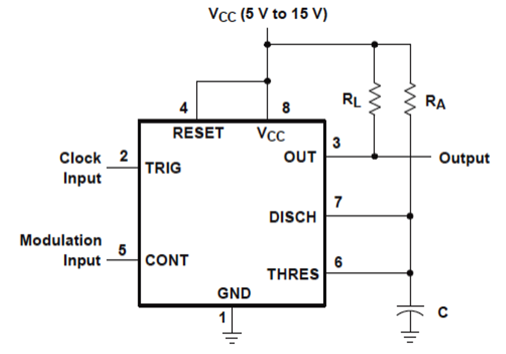
How to Use IC 555 for Generating PWM Outputs | Circuit Diagram Centre

5 Images Cpu Fan Pinout And Review - Alqu Blog

Arduino PWM Fan Controller – Microcontroller Based Projects

Pwm Wiring Diagram